5V O2 Sensor Circuit using LM3914 LED Display for Car Air-Fuel Mixture Meter
5V O2 Sensor Circuit using LM3914 LED Display for Car Air-Fuel Mixture Meter - Oxygen (O2) sensors are used to sense the amount of oxygen in the exhau

5V O2 Sensor Circuit using LM3914 LED Display for Car Air-Fuel Mixture Meter - Oxygen (O2) sensors are used to sense the amount of oxygen in the exhaust gases.
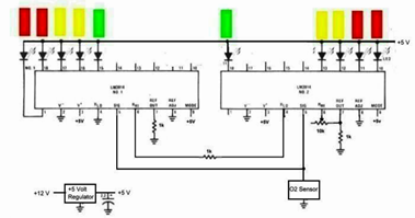
The following circuit uses two LM3914s Dot/Bar Display Driver IC for the LED display. This O2 sensor circuit will be used as air fuel mixture meter of cars.
» 1998 Lexus ES300 EWD Circuit Schematic
» Fire Smoke Detector Circuit Diagram Operation System
» TLE4241GM LED Driver Typical Application Circuit Schematic
» LM1819 Automotive Tachometer Application Circuit Diagram and Datasheet
» MC33099 for Three-phase Alternator Automotive Voltage Regulator Circuit System
This sensor operates at 5V regular supply, uses 1/4 Watt 1K resistors, 10V 2.2 or 4.7 uF filter capacitor and 0.95V potentiometer on pin 6 of LM3914 which will cause the last LED to turn on when the input from the sensor exceeds 0.95V.
To prevent over voltage of the battery, it uses regulator which also has an internal thermal sensing circuit that limits the current output to avoid damaging the regulator.
Detailed explanation on 5V O2 Sensor Circuit using LM3914 LED Display for Car Air-Fuel Mixture Meter can be seen here in the pdf filetype (source: buckeyetriumphs.org)
Tags: air fuel meter, o2 sensors, LM3914 application,
Related 5V O2 Sensor Circuit using LM3914 LED Display for Car Air-Fuel Mixture Meter Posts in Automotive Category» 1998 Lexus ES300 EWD Circuit Schematic
» Fire Smoke Detector Circuit Diagram Operation System
» TLE4241GM LED Driver Typical Application Circuit Schematic
» LM1819 Automotive Tachometer Application Circuit Diagram and Datasheet
» MC33099 for Three-phase Alternator Automotive Voltage Regulator Circuit System
Copyright www.unboxing.eu.org
