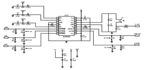
The AD9662 Laser Diode Driver Evaluation Board Schematic and Datasheet
The AD9662 Laser Diode Driver Evaluation Board Schematic and Datasheet - This schematic below was built using a 2-layer evaluation board for the AD966

The AD9662 Laser Diode Driver Evaluation Board Schematic and Datasheet - This schematic below was built using a 2-layer evaluation board for the AD9662 3-Channel Laser Diode Driver,this device are used mainly for high performance CD-DVD recordable drives and laser diode current switching.
If you choose dc logic levels on the enable pins, use all Jumper W1 through Jumper W5 while Resistor R6 through Resistor R11 should not be installed.
Otherwise, when you desired an external signal sources on the enable pins, used all these resistors while the jumper is disabled.
Find complete AD9662 features, AD9662 general description, pin function configuration and description instead of this Laser Diode Driver Evaluation Board Schematic in the AD9662 datasheet.
Tags: AD9662 datasheet, Laser Diode Driver,
Related The AD9662 Laser Diode Driver Evaluation Board Schematic and Datasheet Posts in Laser Driver Category» Great and Rapid Laser Driver Circuit for Multi-Function Integrated Laser Driver
Copyright www.unboxing.eu.org
