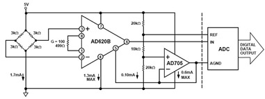
Pressure Transducer Bridge Monitor Circuit Diagram using AD620
Pressure Transducer Bridge Monitor Circuit Diagram using AD620 - A 3kOhms pressure transducer bridge that operates on a 5V single supply is shown in t

Pressure Transducer Bridge Monitor Circuit Diagram using AD620 - A 3kOhms pressure transducer bridge that operates on a 5V single supply is shown in the figure below.
Where small size and low power become more significant, the AD620 is suitable for higher resistance and pressure sensors powered at lower voltages.
In the circuit like this, bridge consumes only 1,7mA. The using of AD620 and a buffered voltage divider allows the signal to be conditioned for only 3.8mA of total supply current.
If you need to see the AD620 datasheet, you can find it here in this blog (source: analog.com).
Tags: pressure monitor, AD620 application,
Copyright www.unboxing.eu.org
