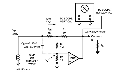
Op Amp Classic Gain and Linearity Testing Circuit Diagram
Op Amp Classic Gain and Linearity Testing Circuit Diagram - Diagram below shows you with a classic test fixture that has been used for long periods in

Op Amp Classic Gain and Linearity Testing Circuit Diagram - Diagram below shows you with a classic test fixture that has been used for long periods in order to give anyone for resolving the non-linearity errors for operational amplifiers.
In this op amp gain test circuit, Rin and Rf are used to give the input voltage for causing an output voltage of 20V p-p (surely can be seen on oscilloscope).
R3 and R4 are used for magnifying error voltage by a factor of ~1000, the ratio of R3 to R4.By this setting, one will avoid the need for a low-noise preamp.
Tags: Operational Amplifier, low-noise preamp, linearity op amp, test fixture, oscilloscope, gain test
Copyright www.unboxing.eu.org
