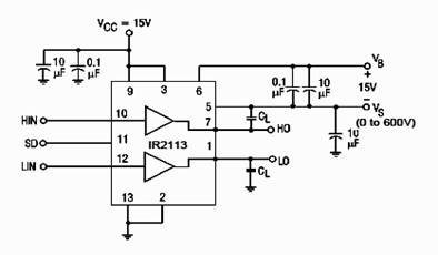
IR2113 Switching Time Test Circuit Schematic
IR2113 Switching Time Test Circuit Schematic - The schematic diagram below appears IR2113 High and Low Side Driver Switching Time Test Circuit

IR2113 Switching Time Test Circuit Schematic - The schematic diagram below appears IR2113 High and Low Side Driver Switching Time Test Circuit.
This IR2113 test circuit can be used for measuring the dynamic electrical characteristics.
According to the IR2113 datasheet, this device is a high voltage, high speed power MOSFET and IGBT driver with independent high and low side referenced output channels.
Tags: power igbt, test circuit, IR2113 datasheet, IR2113 Side Driver, IGBT driver
Copyright www.unboxing.eu.org
