Tweeter Guardian Circuit Diagram
Tweeter Guardian Circuit
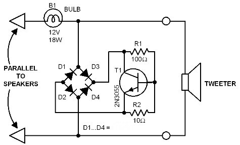
Small but very useful. This circuit provides protection to your tweeter specially when they are always driven near the maximum level. The first circuit uses a simple bulb as a load. This bulb will glow when the signal going to the tweeter reaches a certain preset threshold level.
The bulb functions like a positive temperature coeficient (PTC) resistor - meaning its resistance increases proportionally to its temperature. At around 5.5, the transistor 2N3055 will conduct and shorts the tweeter's input line to ground, thereby preventing the overloading of the tweeter.
 |
| Tweeter Guardian Circuit Diagram |
Tweeter Guardian Circuit
Small but very useful. This circuit provides protection to your tweeter specially when they are always driven near the maximum level.
The first circuit uses a simple bulb as a load. This bulb will glow when the signal going to the tweeter reaches a certain preset threshold level.
The bulb functions like a positive temperature coeficient (PTC) resistor - meaning its resistance increases proportionally to its temperature.
At around 5.5, the transistor 2N3055 will conduct and shorts the tweeter's input line to ground, thereby preventing the overloading of the tweeter.
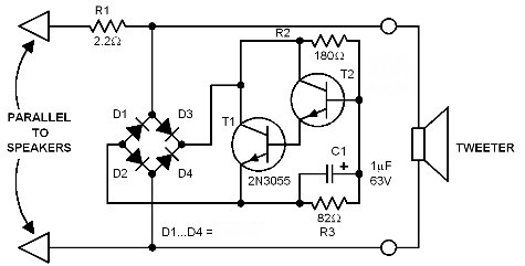
The second circuit is an improved version. A fixed resistor replaces the bulb and the switch transistor is a darlington pair with a delay capacitor.
The circuit still functions like the first circuit. However, due to the capacitor, the circuit will not react to a single overload peak.
This circuit is usually installed inside high power boxes like those in disco applications where equipments are commonly driven to their maximum ratings.


