Automatic Battery Charger Circuit Diagrams
Automatic Battery Charger Circuit Diagrams
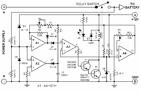
The charging technique applied in this circuit is very simple and straightforward. The circuit closes a relay to connect the charging line to the battery. Once the battery voltage reaches 13.8V, the relay is deactivated and the charging is stopped. The relay will be closed again (charging resumed) when the battery voltage is less than 12.6V. The relay must be able to handle at least 5 amperes.
To calibrate the circuit, first set P1 to minimum so that the relay closes and the battery is charged. Once the battery voltage is 13.8 volts, adjust P1 until the relay opens. Use the battery normally to discharge it until the voltage is around 12.5V, then set P2 so that the relay closes once again.
 |
| Automatic Battery Charger Circuit Diagrams |
Automatic Battery Charger Circuit
The charging technique applied in this circuit is very simple and straightforward. The circuit closes a relay to connect the charging line to the battery.
Once the battery voltage reaches 13.8V, the relay is deactivated and the charging is stopped. The relay will be closed again (charging resumed) when the battery voltage is less than 12.6V.
The relay must be able to handle at least 5 amperes. To calibrate the circuit, first set P1 to minimum so that the relay closes and the battery is charged.
Once the battery voltage is 13.8 volts, adjust P1 until the relay opens. Use the battery normally to discharge it until the voltage is around 12.5V, then set P2 so that the relay closes once again.
