VLF Converter Circuit Diagrams
VLF Converter Circuit
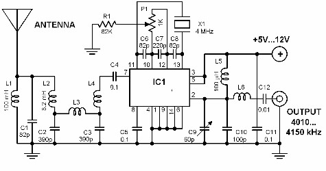
Did you know that there are broadcast stations below 150 kHz? Yes, indeed there are such stations and they are broadcasting in the so called very low frequency band (VLF).
These are the so called low wave stations and you can hear them by using a special converter. The circuit shown above is one such converter.
It converts the frequency of the low wave stations broadcasting between 10 and 150 kHz to the shortwave range of 4.01 up to 4.15 MHz.
This means that you must use your shortwave radio to hear the VLF band.
 |
| VLF Converter Circuit Diagrams |
VLF Converter Circuit
Did you know that there are broadcast stations below 150 kHz? Yes, indeed there are such stations and they are broadcasting in the so called very low frequency band (VLF).
These are the so called low wave stations and you can hear them by using a special converter. The circuit shown above is one such converter.
It converts the frequency of the low wave stations broadcasting between 10 and 150 kHz to the shortwave range of 4.01 up to 4.15 MHz.
This means that you must use your shortwave radio to hear the VLF band.
This technique of up-converting a signal to enable the use of a widely available receiver is very much cheaper than building a special receiver that directly processes the original signal.
Coupling the converter to the SW receiver is very simple. The output of the converter is connected in a straightforward manner to the antenna terminals of the shortwave receiver.
No need to connect wires inside the radio. The channel selection is done through P1. The trimmer capacitor C1 must be adjusted to produce a maximum output.
For the antenna, you can use a piece of wire. The longer the wire, the better.
