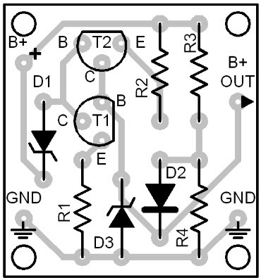
Stable Z Voltage Source Circuit Diagram
Stable Z Voltage Source Circuit
An ordinary power supply normally suffers from high dissipation levels.It happens when the output voltage is set at low level while the input level remains at maximum.
The resulting difference voltage then "fries" the regulator circuit's power transistor continuously. This shortens the life expectancy of the transistor. Also, the heat build up in such regulators is very high that an internal air blower is almost always needed.
 |
| Stable Z Voltage Source Circuit Diagram |
Stable Z Voltage Source Circuit
An ordinary power supply normally suffers from high dissipation levels.It happens when the output voltage is set at low level while the input level remains at maximum.
The resulting difference voltage then "fries" the regulator circuit's power transistor continuously.
This shortens the life expectancy of the transistor. Also, the heat build up in such regulators is very high that an internal air blower is almost always needed.
The power supply featured here does not know this kind of problem since it has an automatic dissipation limiter.
The actual limiter circuit is composed of the components T1, T2, D5, D6, D7 between the transformer and the regulator stages.
The triac T2 must be selected properly to handle the maximum current and dissipated power that will load on it. You can use the table at the end pages of this book to select the needed triac.
The potentiometer P1 in the regulator stage is the normal output voltage adjuster. The output can be varied from 5 up to 50 volts. The triac T2 and the power transistor T4 are to be installed on heatsinks outside the circuit board.
The potentiometer P1 must also be installed outside the circuit board. Make sure to wire these external components correctly.
Take note that two terminals of the potentiomenter P1 are shorted together. See Fig. 55.2 for details.


