Power Supply Regulator Circuit Diagrams
Power Supply Regulator Circuit
. Most modern power supply regulators are contructed using ICs and work more precisely. However some applications do not really require the precision of an IC.
Sometimes discrete components are enough to provide the needed stability.
As a hobbyists you are more interested in constructing circuits which present more challenge and chance to understand its working principles.
Circuits with discrete components are more fun than ready made, ready to use ICs.
 |
| Power Supply Regulator Circuit Diagrams |
Power Supply Regulator Circuit
Most modern power supply regulators are contructed using ICs and work more precisely. However some applications do not really require the precision of an IC.
Sometimes discrete components are enough to provide the needed stability.
As a hobbyists you are more interested in constructing circuits which present more challenge and chance to understand its working principles.
Circuits with discrete components are more fun than ready made, ready to use ICs.
The circuit featured here is designed to give an output voltage of 12V. What is special with this circuit is that it has a current limiter circuit and a constant current source.
The current output is limited up to 0.5A. The constant current source (this function is done by a single FET T1) delivers a maximum of 18 mA to the power transistor T1.
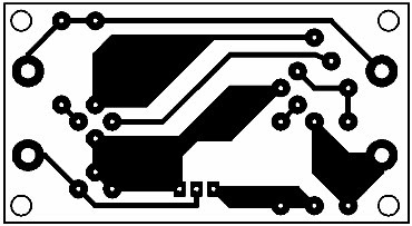
The output voltage of this power supply is variable through the potentiometer P1. The potentiometer must be wired outside of the circuit board.
Be careful in connecting the pot P1 to the circuit board. Never interchange the terminal connections. See Fig. 54.2 for wiring layout.


