Overvoltage Crowbar Circuit Diagrams
Overvoltage Crowbar Circuit
Simple but very effective. This very simple circuit can protect a main circuit which is sensitive to overvoltages.
The first circuit uses a zener diode in parallel to the power line of the protected circuit or device.
Once the output of the power supply increases due to a malfunction, the excess voltage will be routed to ground by the zener diode.
If the voltage will increase further, the total current consumption will exceed the capacity of the fuse. The fuse will blow at this moment and the current supply is broken.
 |
| Overvoltage Crowbar Circuit Diagram #1 |
Overvoltage Crowbar Circuit #1
Simple but very effective. This very simple circuit can protect a main circuit which is sensitive to overvoltages.
The first circuit uses a zener diode in parallel to the power line of the protected circuit or device.
Once the output of the power supply increases due to a malfunction, the excess voltage will be routed to ground by the zener diode.
If the voltage will increase further, the total current consumption will exceed the capacity of the fuse. The fuse will blow at this moment and the current supply is broken.
The zener voltage of the zener diode must be 1 or 2 volts higher than the correct supply voltage and must have a higher current rating than the fuse.
Of course the maximum allowable supply voltage of the protected circuit must be taken into account.
For example if the supply voltage must be 15 volts and the maximum allowable voltage of the protected circuit is 18 volts, then a zener diode of 18 volts must be used.
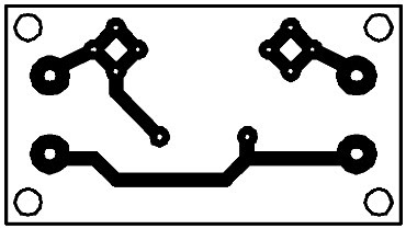
Printed Circuit Overvoltage Crowbar #1
Parts Placement Layout Overvoltage Crowbar #1
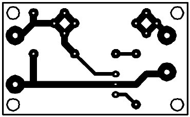
Overvoltage Crowbar Circuit #2
 |
| Overvoltage Crowbar Circuit Diagram #2 |
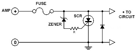
The second circuit can be used for higher current ratings. The low current zener diode triggers the SCR when the supply voltage exceeeds the safe level.
AS a result, the SCR shorts the fuse to ground thereby blowing it. The resistor R limits the trigger current and the zener current flowing through the diode.
The approximate value of R can be found by using this simple formula:
R = ( Zener diode's voltage - SCR's trigger voltage)/( SCR's trigger current )
Of course, you have to select the right SCR type for your particular application. Use the tables at the end pages of this book.


