Active Impedance Converter Circuit Diagram
Active Impedance Converter Circuit
Coupling two electronic modules with different impedance values together will produce sub-optimal results, unless you provide an impedance converter between the two.
Simple impedance conversion can be done by arranging resistors in certain ways. However, this resistor array attenuates the signal being passed through, resulting to signal losses.
To avoid losses within the impedance converter, an active circuit is usually used. An active impedance converter not only compensates for the losses, it can also amplify the signal if desired.
The two circuits featured here use common OPAMP integrated circuits. They are easy to construct and use.
Diagram 42.0 shows a 75-75 ohm active converter. Since the impedances are not changed, this circuit actually works as a buffer. If dimensioned properly, it will provide some amplification.
 |
| Active Impedance Converter Circuit Diagram |
Active Impedance Converter Circuit
Coupling two electronic modules with different impedance values together will produce sub-optimal results, unless you provide an impedance converter between the two.
Simple impedance conversion can be done by arranging resistors in certain ways. However, this resistor array attenuates the signal being passed through, resulting to signal losses.
To avoid losses within the impedance converter, an active circuit is usually used. An active impedance converter not only compensates for the losses, it can also amplify the signal if desired.
The two circuits featured here use common OPAMP integrated circuits. They are easy to construct and use.
Diagram 42.0 shows a 75-75 ohm active converter. Since the impedances are not changed, this circuit actually works as a buffer. If dimensioned properly, it will provide some amplification.
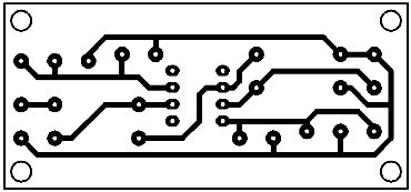
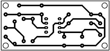
Printed Circuit Active Impedance Converter #1
Parts Placement Layout Active Impedance Converter #1
Diagram 42.1 shows a 75-50 converter. It converts a 75 ohm input impedance into a 50 ohms impedance. It is usually used in pulse and video applications.
It is possible to be applied as driver for coaxial cables since it can deliver currents up to 80 mA.
The first circuit amplifies the input signal by a factor of 5. However, it does not convert the impedance.
The second circuit converts the 75 ohm impedance to 50 ohm impedance and at the same time amplifies the input signal by a factor of 5.
The bandwidth of both circuits is 20...30 MHz.


