Running Light Circuit Diagrams
Running Light Circuit Diagram
This circuit controls several LEDs to simulate the effect of a running light. The "running speed" is dependent on the frequency of the clock generator and can be varied with the pot P5.
 |
| Running Light Circuit Diagrams |
Running Light Circuit Diagram
This circuit controls several LEDs to simulate the effect of a running light. The "running speed" is dependent on the frequency of the clock generator and can be varied with the pot P5.When P5 is in the middle position, the frequency is around 6 Hz. How long the LEDs remain lighted is controllable through the potentiometers P1 up to P4.
To make the LEDs appear to "run" smoothly, set all potentiometers (P1 to P4) to the same position.
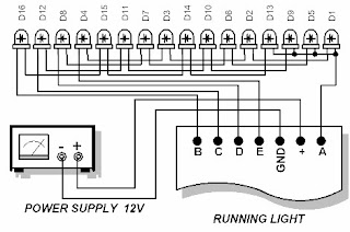
Figure 92.2 below shows how you must arrange the LEDs to achieve the best effect. If you desire to use this circuit to control high current lamps or triacs, replace the LEDs with optocouplers.
The internal LEDs of the optocouplers will then replace the normal LEDs.
The optocouplers will act as isolated relays to trigger higher current capacity switches or relays.


