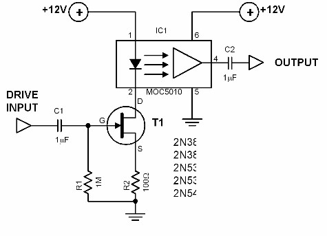
Line Optocoupler Circuit Diagram
Line Optocoupler
Optocouplers are highly valuable in electronics as isolators in power supply circuits, audio input/output, medical applications, etc.
An optocoupler like the special IC used in the featured circuit has a typical isolation resistance of 1011 ohms.
 |
| Line Optocoupler Circuit Diagram |
Line Optocoupler
Optocouplers are highly valuable in electronics as isolators in power supply circuits, audio input/output, medical applications, etc.
An optocoupler like the special IC used in the featured circuit has a typical isolation resistance of 1011 ohms.
The principle of an optocoupler is very simple: the changes in the input current produce corresponding changes in the output current.
The input circuit is, however, electrically and galvanically isolated from the output circuit.
The signal transfer is done through the use of either light, laser, or infrared transmitter and receiver packaged and sealed in a single unit.
The circuit shown is an optocoupler driver and has an amplification factor of 0.75. The maximum input voltage must not exceed 2Vrms.
Its bandwidth is 118 kHz. The FET in the circuit works as voltage to current converter. As is usual with optocoupler circuits, each side must have its own supply line.
Otherwise, the desired high degree of isolation will not be achieved.
Signal transfer is done via optical transmission.

