Hardware Screensaver Circuit Diagram
Hardware Screensaver
This circuit enables you to connect four monitors to a single graphic card. The type of the graphic card used is not important (be it VGA, EGA, CGA or Hercules) as long as the logic levels are TTL compatible.
 |
| Hardware Screensaver Circuit Diagram |
Hardware Screensaver
This circuit enables you to connect four monitors to a single graphic card. The type of the graphic card used is not important (be it VGA, EGA, CGA or Hercules) as long as the logic levels are TTL compatible.
The 3-state bus driver IC 74HC541 and the multipin connector shown inside the dotted rectangle must be duplicated for each monitor and wired parallel to the main video bus.
The current consumption is around 10 mA. You must provide a regulated 5 volts to power the circuit.
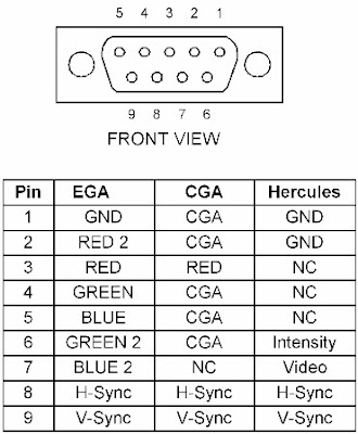
The different signals (RGB and sync) are fed to the 9-pin sub-D male connector. Their lines inside the circuit make up the main bus and each line is normally pulled up to logic 1 by a 1K resistor.
The signals pass through the driver ICs which are permanently wired to conduction. They finally get to the monitor through the 9-pin sub D female connector.
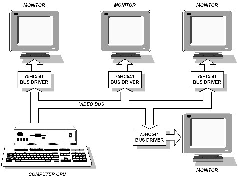
Sample Application of Hardware Screensaver
Figure 80.0 shows a circuit's sample application with four monitors. You can, of course, connect more monitors.
This is highly practical for information systems in large halls, in airports, transportation stations, large offices, stock exchange markets, etc.


