Duty Cycle Generator Circuit Diagrams
Duty Cycle Generator
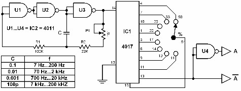
A pulse generator with a variable duty cycle can be easily constructed with only two ICs. This generator is composed of a clock circuit and a decimal divider. The output of the decimal counter can be selected through a rotary switch. The diagram shows the outputs with different duty cycles. The circuit has two final outputs: A and -A(minus A).
 |
| Duty Cycle Generator Circuit Diagrams |
Duty Cycle Generator
A pulse generator with a variable duty cycle can be easily constructed with only two ICs. This generator is composed of a clock circuit and a decimal divider.
The output of the decimal counter can be selected through a rotary switch. The diagram shows the outputs with different duty cycles. The circuit has two final outputs: A and -A(minus A).
The table shows the percentage of the duty cycle at each output. The clock frequency can be varied through potentiometer P1.
If several frequency ranges are desired and you want to be able to change quickly from one range to another, connect several capacitors (for C') through a rotary switch.
The capacitors' values are given in the table.
