48 MHz Clock Generator Circuit Diagram
48 MHz Clock Generator
This clock generator can be applied to serve as timebase for computers. It is crystal controlled to deliver a highly stable signal.
 |
| 48 MHz Clock Generator Circuit Diagram |
48 MHz Clock Generator
This clock generator can be applied to serve as timebase for computers. It is crystal controlled to deliver a highly stable signal.
One advantage of this circuit is that it uses a standard crystal readily available from any electronic supplier. The crystal oscillates at its third overtone between 44 and 52 MHz.
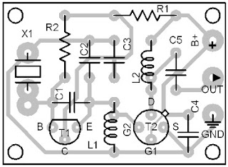
If you want to trim the crystal to be able to fine tune the frequency to exactly 48 MHz (use a frequency counter), add the LC circuit shown.
The 60 pF trimmer capacitor trims the crystal frequency. The insertion point (marked with X in the circuit diagram) must be broken, and the LC circuit inserted to it in series.
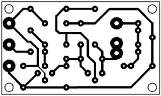
The above printed circuit layouts (Figure 85.2 and Figure 85.3) are designed for the oscillator variant with the additional LC circuit in series to its crystal.
This additional LC circuit makes the oscillation frequency trimmable to an exact value.
The signal that comes out of this circuit (48 MHz) already fits into the HF category.
Thatīs why you must use a shielded cable to feed the signal to the following circuit modules that must be driven by this oscillator.


