DC Voltage Doubler Circuit Diagrams
Doubling a voltage level is sometimes necessary to power a certain circuit. Voltage doubling can be done by the very simple circuit featured here.
 |
| DC Voltage Doubler |
DC Voltage Doubler
Doubling a voltage level is sometimes necessary to power a certain circuit. Voltage doubling can be done by the very simple circuit featured here.
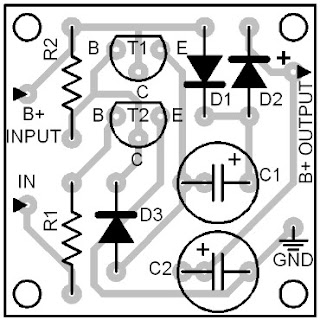
The circuit is controlled by a clock signal of around 10 kHz. The signal´s peak amplitude must be strong enough to trigger the transistor T1 to conduction.
The circuit is controlled by a clock signal of around 10 kHz. The signal´s peak amplitude must be strong enough to trigger the transistor T1 to conduction.
When T2 conducts, the capacitor C1 charges up to the power supply level. When the signal inverts to zero level, transistor T2 shuts off while transistor T1 conducts.
At this moment, the capacitor C2 - which was initially full charged from the power supply line - will be charged some more by the series combination of capacitor C1 and the power supply line.
At this moment, the capacitor C2 - which was initially full charged from the power supply line - will be charged some more by the series combination of capacitor C1 and the power supply line.
After some time, the capacitor C2 will be charged to a level which is almost double the power supply level.
The resistance value of R1 (set to 1K in the diagram) is dependent on the input signal´s amplitude. You must adjust this value to adapt it to a different amplitude level.
The resistance value of R1 (set to 1K in the diagram) is dependent on the input signal´s amplitude. You must adjust this value to adapt it to a different amplitude level.


