Rangkaian Pendeteksi Asap / Alarm Kebakaran
Rangkaian Pendeteksi Asap/ Alarm Kebakaran - Salam para Electrical Engineer yang setia membaca artikel pada blog ini. Semoga tetap bersemangat untuk b
Rangkaian Pendeteksi Asap/ Alarm Kebakaran - Salam para Electrical Engineer yang setia membaca artikel pada blog ini. Semoga tetap bersemangat untuk belajar dan terus belajar tentang elektronika. Pada kesempatan kali ini saya akan berbagi tentang Rangkaian Pendeteksi Asap/ Alarm Kebakaran.
Pada saat terjadi kebakaran tentunya akan menimbulkan asap.. Apabila kita berada di ruangan berbeda maka kita mungkin tidak mengetahui adanya kebakaran di ruang lain. namun jangan khawatir, berikut solusi untuk mengatasi hal tersebut.
Gunakan fitur Translate di sebelah kanan untuk menterjemahkan teks berbahasa inggris, selamat membaca, semoga bermanfaat.
This is a simple Smoke Detector circuit based on a LDR and lamp pair for sensing the fire. It uses a very simple approach to detecting smoke in the air. The alarm works by sensing the smoke produced during fire. The circuit produces an audible alarm when the fire breaks out with smoke.
When there is no smoke the light from the bulb will be directly falling on the LDR.The LDR resistance will be low and so the voltage across it (below .6V).
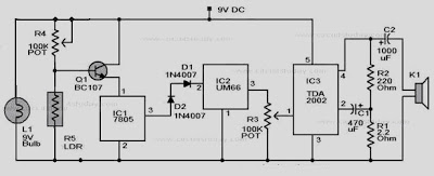
Skema Rangkaian
 |
| Skema Rangkaian Pendeteksi Asap/ Alarm Kebakaran |
This is a simple Smoke Detector circuit based on a LDR and lamp pair for sensing the fire. It uses a very simple approach to detecting smoke in the air. The alarm works by sensing the smoke produced during fire. The circuit produces an audible alarm when the fire breaks out with smoke.
When there is no smoke the light from the bulb will be directly falling on the LDR.The LDR resistance will be low and so the voltage across it (below .6V).
The transistor will be OFF and nothing happens. When there is sufficient smoke to mask the light from falling on LDR, the LDR resistance increases and so do the voltage across it.
Now the transistor will switch to ON.This gives power to the IC1 and it outputs 5V.This powers the tone generator IC2 to play a music.This music will be amplified by IC3 to drive the speaker.
The diode D1 and D2 in combination drops 1.4 V to give the rated voltage (3.5V ) to UM66 .UM 66 cannot withstand more than 4V.
The diode D1 and D2 in combination drops 1.4 V to give the rated voltage (3.5V ) to UM66 .UM 66 cannot withstand more than 4V.
Copyright www.unboxing.eu.org
