Rangkaian Sirene Polisi
Rangkaian Sirene Polisi - Salam para Electrical Engineer yang setia membaca artikel pada blog ini. Semoga tetap bersemangat untuk belajar dan terus be
Rangkaian Sirene Polisi - Salam para Electrical Engineer yang setia membaca artikel pada blog ini. Semoga tetap bersemangat untuk belajar dan terus belajar tentang elektronika. Pada kesempatan kali ini saya akan berbagi tentang Rangkaian Sirene Polisi.
Suara sirene polisi mungkin sudah sangat familiar ditelinga kita. Ada yang merasa cemas dan ada yang merasa aman ketika mendengar sirene polisi tersebut.
Berikut skema rangkaian sirene polisi yang bisa di gunakan pada kendaraan kita. Gunakan fitur translate di sebelah kanan untuk menterjemahkan. Selamat membaca semoga bermanfaat.
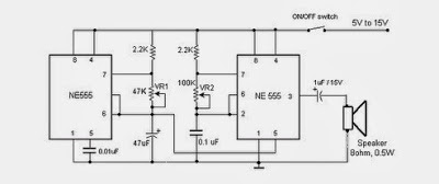
The Circuit consists of 2 pieces IC NE 555 that serves as the frequency (multivibrator astable) that the frequency can be set to play Vr1 and Vr2.
If the sound output in the less hard (loud) you can add a brace power amplifier that has a higher brace misalanya series amplifier LM386. series has a power output greater tegangn and have the same input.
Skema Rangkaian
 |
| Skema Rangkaian Sirene Polisi |
The Circuit consists of 2 pieces IC NE 555 that serves as the frequency (multivibrator astable) that the frequency can be set to play Vr1 and Vr2.
If the sound output in the less hard (loud) you can add a brace power amplifier that has a higher brace misalanya series amplifier LM386. series has a power output greater tegangn and have the same input.
To install this series you just menghubungakan output rangkain sirens and then enter in to the input. Move the speaker to the output ampilifier LM386.
Functions of each pin IC 555:
Functions of each pin IC 555:
 |
| IC 555 |
- Ground, is the input pin of the source of the negative DC voltage
- trigger, negative input from the lower comparators (comparator B) that maintain oscillation capacitor voltage in the lowest 1 / 3 Vcc and set RS flip-flop
- output, the output pin of the IC 555.
- reset, the pin that serves to reset the latch inside the IC to be influential to reset the IC work. This pin is connected to a PNP-type transistor gate, so the transistor will be active if given a logic low. Normally this pin is connected directly to Vcc to prevent reset
- control voltage, this pin serves to regulate the stability of the reference voltage negative input (comparator A). This pin can be left hanging, but to ensure the stability of the reference comparator A, usually associated with a capacitor of about 10nF to berorde pin groun
- threshold, this pin is connected to the positive input (comparator A) which will reset the RS flip-flop when the voltage on the capacitor from exceeding 2 / 3 Vc
- discharge, this pin is connected to an open collector transistor Q1 is connected to ground emitternya. Switching transistor serves to clamp the corresponding node to ground on the timing of certain
- vcc, pin it to receive a DC voltage supply. Usually will work optimally if given a 5-15V. the current supply can be seen in the datasheet, which is about 10-15mA.
Copyright www.unboxing.eu.org
